Understanding the Basics of Public Safety Networks 

Public safety networks are the backbone of emergency response, law enforcement, and disaster management. These dedicated communication systems provide first responders with the tools they need to coordinate efforts during critical situations. In this blog, we’ll explore the essential aspects of public safety networks, emphasizing their importance, the role of RF (Radio Frequency) engineering, and the various communication technologies employed in these networks. 

Importance and Role of Public Safety Networks 

Public safety networks play a pivotal role in ensuring the safety of the public and the effectiveness of first responders. When a 911 call comes in or an emergency incident occurs, improved communication can be a matter of life and death. These networks enable first responders to share critical information, coordinate their actions, and respond rapidly to incidents, making them indispensable in times of crisis. 

Navigating RF Propagation 

RF engineering, or Radio Frequency engineering, is at the heart of public safety networks. RF engineers design, deploy, and maintain wireless communication systems that operate in the radio frequency spectrum. To understand these networks, it’s essential to grasp key RF concepts: 

Signal: Information transmitted wirelessly, carrying voice, data, or video. 

Frequency: Measured in Hertz (Hz), it refers to the number of complete cycles of a waveform in one second. 

Wavelength: The physical distance covered by one complete cycle of a waveform, usually measured in meters (m). 

Amplitude: Indicates the magnitude or strength of the RF signal. 

Band: A portion of the electromagnetic spectrum within which radio signals can be transmitted and received. 

Understanding these concepts is crucial for managing and optimizing RF signals in public safety networks. 

Public Safety Radio Spectrum 

Public safety agencies rely on specific frequency bands to ensure reliable and interference-free communication. These bands are chosen based on their characteristics: 

VHF (Very High Frequency): Suitable for long-distance communications and often used in rural areas. 

UHF (Ultra High Frequency): Offers better indoor coverage and is widely used in urban settings. 

700 MHz: Strikes a balance between coverage and capacity, often chosen for nationwide networks. 

800 MHz: Offers high capacity and is used in densely populated areas. 

Selecting the right frequency band is a critical decision in network design, ensuring that coverage meets the specific needs of each environment. 

Communication Technologies in Public Safety Networks 

Public safety networks employ various communication technologies to ensure effective communication. These technologies include: 

P25 (Project 25): A suite of standards designed to enable secure and interoperable digital radio communication systems. P25 is commonly used by federal, state, and local public safety agencies in the United States and has seen adoption in several other countries worldwide, including Canada, Australia, New Zealand, Brazil, India, and Russia. 

LTE (Long-Term Evolution): A high-speed wireless communication standard providing fast data rates, quality of service (QoS), priority and preemption mechanisms, security features, and interoperability. LTE is essential for supporting real-time video streaming and data sharing in the field. It is widely used globally, including in countries like the United States, Canada, the United Kingdom, and Australia. 

Tetra (Terrestrial Trunked Radio): A digital mobile radio standard optimized for professional mobile radio systems, providing features like group communication, presence information, and call priority. Tetra is widely used in public safety and other professional sectors, particularly in Europe and other parts of the world. 

Understanding where each technology shines helps public safety agencies make informed decisions about their network infrastructure. 

The Importance of Network Planning 

Network planning is a crucial task in the network deployment or optimization processes. With proper network planning, you will ensure your public safety networks will work properly and will be deployed in the lowest time and cost possible. The process is typically as follows:  

Survey > Design > Verify > Maintain 

The Role of Network Surveys and Grid Tests 

Ensuring reliable network coverage is paramount in public safety. Network surveys and grid tests are indispensable tools. Network surveys meticulously examine signal strength, quality, and coverage, while grid tests verify that network coverage meets specific requirements in each cell. 

These assessments help identify coverage gaps, interference sources, and other network issues, empowering you to make data-driven decisions to enhance network performance and reliability and ultimately get your Public Safety Network approved by the Authorities Having Jurisdiction. 

The Significance of Network Design 

Network design is the bedrock of a robust Public Safety Network. It involves strategically planning the placement and configuration of network components to achieve desired coverage, capacity, and reliability. Network design ensures that critical areas have radio coverage spanning 99% of the floor area. 

Furthermore, network design is pivotal in ensuring network resilience. Notwithstanding, redundancy, backup power systems, and disaster recovery plans are essential requirements to maintain network availability and reliability, even during power outages or emergencies. 

With proper network design, you also save a lot of money and time as you minimize the need for further network optimizations and the time to deploy, which are often costly and time-consuming. 

How iBwave Helps 

Plan your Public Safety Networks for approvals quickly and effectively! iBwave offers specialized solutions for surveying, grid testing and designing public safety networks. Our tools streamline the network survey and design process, ensuring that it meets all regulatory compliance and safety requirements.  

Learn more about iBwave Mobile Survey if you’re looking for a seamless and cost-effective solution for network surveying and grid testing or explore iBwave Public Safety, a software trusted by over 90% of the public safety market for designing the most reliable public safety networks! 

With iBwave’s solutions, you can design and maintain networks that meet the needs of first responders and gain authorities’ approval! 

Eager to Learn More? 

If you want to learn more, take our free online course on the RF Fundamentals for Public Safety Networks! This one-hour course is a great fit for everyone from RF engineers to field technicians, students, or telecom journalists, who want to enhance their knowledge of public safety networks.  

Streamlining Public Safety Network Design with Uplink Output Maps

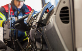
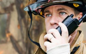
Uplink capabilities are crucial in (P25, TETRA, TEDS or DMR) public safety networks. When first responders are in a potentially dangerous situation, such as firefighters inside a burning building, ensuring they can transmit information can be the difference between life and death. This makes uplink mapping a mission-critical requirement for all public safety wireless network designs.

Accurate mapping is necessary to ensure those uplink capabilities are reliable. Signals can be lost or diluted for a variety of reasons, all of which need to be identified in advance by sophisticated mapping tools capable of capturing the important nuances and performing the necessary calculations.

These calculations are highly complex and can be difficult for employees of Authorities Having Jurisdiction (AHJ – in the USA) or any other authorities in respectable countries and regions to interpret. Interpretation becomes particularly difficult when the data is packaged in traditional spreadsheet formats.

iBwave Public Safety resolves these issues with the addition of two new uplink output maps to the suite of previously released uplink maps, built on the foundation of the uplink-at-antenna map. Leveraging the uplink received signal strength indicator (RSSI) map added in the last release, the two new uplink automated gain control (AGC) and Near-Far Effect maps will make life easier both for designers and authorities by delivering three key benefits:

Simplified design process

More straightforward approval process

Accelerated implementation

RSSI Map Calculates Gain/Loss Anywhere in the Network

Manually calculating signal gain or loss is a highly difficult and complex task, requiring designers to account for gain or loss from hardware, including signal splitters, antennas, cables, and bi-directional amplifiers (BDAs), as well as from obstacles such as walls. Our uplink RSSI map performs these calculations automatically, displaying the cumulative gain or loss from all these network elements at any given point on the map.

Beyond the calculations themselves, the visual format of the map provides two key benefits. For designers, the visual representation is easy to interpret, which makes it easier to accurately assess the functionality of a network design. And since the maps are easily modified, they can quickly refine a network design as needed.

The visual representation also assists with the authorities’ approval process. Network design reviews are often done by staff who don’t have technical training, and network data historically has been in the form of dense, difficult-to-interpret Excel spreadsheets. Maps are clear and easy to interpret, ensuring the best possible chance of approval.

Watch a demo of our Uplink RSSI Map feature below:

AGC Map Clearly Visualizes Gain Control

Gain control is a necessity for any wireless network. But it can affect the functioning of devices within that network, potentially causing some to not function. The new AGC map visualizes any gain control that will happen in a network.

This feature helps network designers address both overdesign and, crucially for public safety, under design. An overdesigned network is less budget efficient and is best avoided. But under design in public safety can mean the failure of mission-critical communications. This can be the difference between life and death for first responders or the people they’re helping.

Visualization makes it easy for designers to catch both overdesign and under design, while the easily modified maps make it straightforward to make adjustments and check them during the design process.

Near-Far Effect Map Captures Crucial Nuances

The near-far effect map shows when the proximity of one device to an antenna causes signal attenuation that affects a device that’s further away. When the signal strength gets modulated for the device closer to an access point, further devices in areas of poorer connectivity can lose their connection entirely.

Our near-far effect map captures this crucial nuance in public safety network design. Building off our AGC map, it gives designers the ability to accurately predict this more subtle cause of uplink failure.

And by presenting the information in a clear and comprehensive manner, it ensures the best possible chance of design approval by authorities. Rather than having to rely on heuristics, such as standardized antenna spacing that may not be relevant in a given deployment, an authorized employee can simply look at the map to see any potentially problematic areas. By avoiding dense, difficult-to-understand Excel spreadsheets, it minimizes the chance of misinterpretation of data.

Watch a demo of our Near-far Effect and Uplink AGC maps below:

iBwave Offers Comprehensive Uplink Mapping Capabilities for Network Designers

iBwave Public Safety design solutions put a full suite of uplink mapping tools into the hands of public safety network designers.

Interactive maps clearly show signal strength for designers and authorities and make it easy for designers to make changes and corrections during the design process. Easy-to-interpret maps ensure the best possible chance of success during the approval process and shortest possible turnaround time, accelerating implementation. We’ve also introduced a complete solution that simplifies surveying and grid testing public safety networks. Now you can get everything for surveying, grid testing and designing public safety networks under one family of iBwave products.

Check out our full range of public safety solutions for design and survey.

Meet iBwave Public Safety

While we have always been in the business of providing software to design Public Safety networks, it’s always been within the context of using our iBwave Design software – you know, the one that designs every wireless network under the sun.

But over the last couple of years, we started to notice an increase in interest in the design of public safety networks, and all you have to do is think about large emergency situations, think about the amount of data traffic – videos, voice, audio, and otherwise – flowing through the public safety networks between all first responder teams, and see why they are so important.

Simply put, without a well-designed public safety network, it can be extremely difficult for first responders to communicate vital information to and from each other. And when the ability to communicate in an emergency situation is compromised, so are people’s lives.

So Why Use this Software to Design your Public Safety Networks?

Some of you already familiar with iBwave might be wondering what’s different about this particular software – and the answer is pretty simple: it is targeted at those who are only designing public safety networks. And while you can still design public safety networks using iBwave Design, and all features in this software will be in that one – for those who only design public safety networks, this would be the best software for them to use.

Let’s talk about the specific public safety features we’ve added into this software, as well as iBwave Design.

Critical/General Zone Identification

In public safety certain guidelines need to be adhered to – in particular, you need to have -95dBM in 90% of ‘General’ area, and ‘Critical’ areas need to be -95 dBM as well, but 99%. With the new iBwave Public Safety software, you can identify both the ‘General and ‘Critical’ zones within your design and set the different compliance requirements for each area.

So for example, in the below – the ‘General’ area has been defined as well as select ‘Critical’ areas (equipment room, lobby, emergency exit, etc). Once that is done, you can right click on the area and select ‘Compliance Area Properties’ and then set your requirements for each area : General -95 dBm, 95% and Critical -95dBm, 99%. Then when you run your prediction, your compliance in each of the areas will show.

Here’s a short video of setting the different areas with different requirements. To do it you just select either one area, or all the same areas, right click and set up the compliance criteria. Then when you run your prediction, you will see the compliance labels telling you how they will perform.

Donor Isolation

A common challenge is feedback because you don’t have enough isolation between your donor and serving antennas – the donor antenna often picks up the signal of its own DAS network almost as clearly as the macro signal, which causes a feedback loop and renders the network unusable. A big problem when designing public safety networks.

To know things will work as they need to, guidelines are in place that stipulate you need -20 dB of isolation between donor and server antennas. To help with this, we’ve added this new ‘Donor Isolation’ feature which will calculate and show you the isolation dB and whether it meets the criteria of -20.

Here’s a short video showing you this. In it, I just go over to the predictions area and select ‘Donor Isolation’ – from there I can validate my design, and it will give me a result. As you can see the result shows -17.41 dB, which does not meet the -20 dB guideline and therefore it’s a fail. In this case, you would know you would need to adjust your design, and re-validate until you get a pass. Unfortunately, the feature to print a smiley face sticker out when successful didn’t make it into this version.

What’s Next for iBwave Public Safety?

The new iBwave Public Safety software is a great start, but it’s just that – only the start of what we intend to be a long roadtrip along the public safety highway. We’ve got a roadmap, we’ve got a development team, and we’ve got great customers to give us the right input to keep improving.

Interested in Learning More?

You can read all about iBwave Public Safety by heading over to the product page, found here. From there you can take a look at the datasheet, watch a demo video of it in action, and reach out to our team with any specific questions you may have.

Wirelessly yours,

Kelly

Exit mobile version