
Streamlining Public Safety Network Design with Uplink Output Maps
Share
Uplink capabilities are crucial in (P25, TETRA, TEDS or DMR) public safety networks. When first responders are in a potentially dangerous situation, such as firefighters inside a burning building, ensuring they can transmit information can be the difference between life and death. This makes uplink mapping a mission-critical requirement for all public safety wireless network designs.
Accurate mapping is necessary to ensure those uplink capabilities are reliable. Signals can be lost or diluted for a variety of reasons, all of which need to be identified in advance by sophisticated mapping tools capable of capturing the important nuances and performing the necessary calculations.
These calculations are highly complex and can be difficult for employees of Authorities Having Jurisdiction (AHJ – in the USA) or any other authorities in respectable countries and regions to interpret. Interpretation becomes particularly difficult when the data is packaged in traditional spreadsheet formats.
iBwave Public Safety resolves these issues with the addition of two new uplink output maps to the suite of previously released uplink maps, built on the foundation of the uplink-at-antenna map. Leveraging the uplink received signal strength indicator (RSSI) map added in the last release, the two new uplink automated gain control (AGC) and Near-Far Effect maps will make life easier both for designers and authorities by delivering three key benefits:
RSSI Map Calculates Gain/Loss Anywhere in the Network
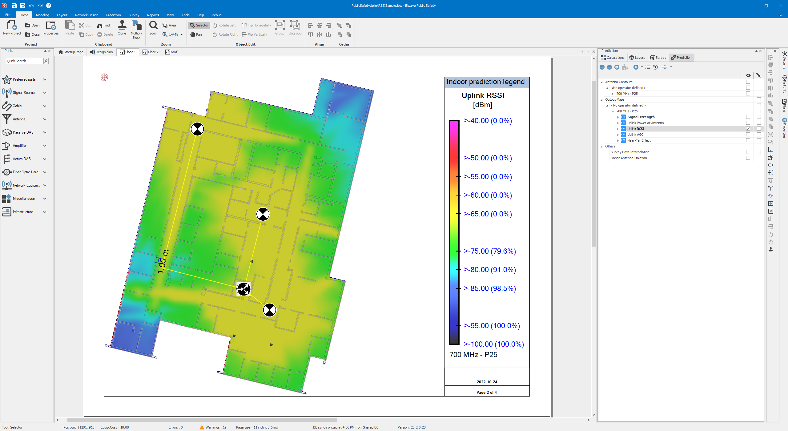
Manually calculating signal gain or loss is a highly difficult and complex task, requiring designers to account for gain or loss from hardware, including signal splitters, antennas, cables, and bi-directional amplifiers (BDAs), as well as from obstacles such as walls. Our uplink RSSI map performs these calculations automatically, displaying the cumulative gain or loss from all these network elements at any given point on the map.
Beyond the calculations themselves, the visual format of the map provides two key benefits. For designers, the visual representation is easy to interpret, which makes it easier to accurately assess the functionality of a network design. And since the maps are easily modified, they can quickly refine a network design as needed.
The visual representation also assists with the authorities’ approval process. Network design reviews are often done by staff who don’t have technical training, and network data historically has been in the form of dense, difficult-to-interpret Excel spreadsheets. Maps are clear and easy to interpret, ensuring the best possible chance of approval.
Watch a demo of our Uplink RSSI Map feature below:
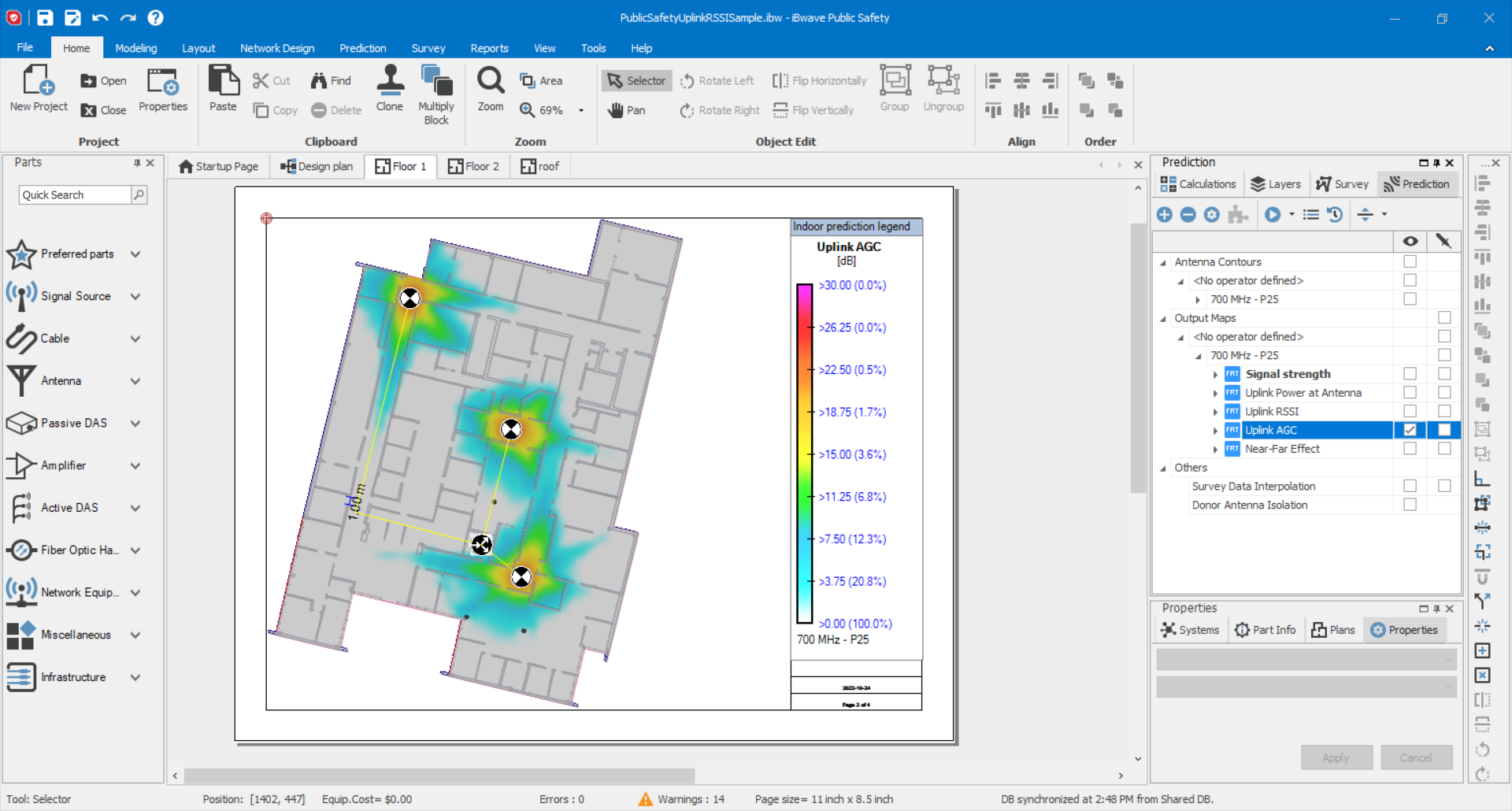
AGC Map Clearly Visualizes Gain Control
Gain control is a necessity for any wireless network. But it can affect the functioning of devices within that network, potentially causing some to not function. The new AGC map visualizes any gain control that will happen in a network.
This feature helps network designers address both overdesign and, crucially for public safety, under design. An overdesigned network is less budget efficient and is best avoided. But under design in public safety can mean the failure of mission-critical communications. This can be the difference between life and death for first responders or the people they’re helping.
Visualization makes it easy for designers to catch both overdesign and under design, while the easily modified maps make it straightforward to make adjustments and check them during the design process.
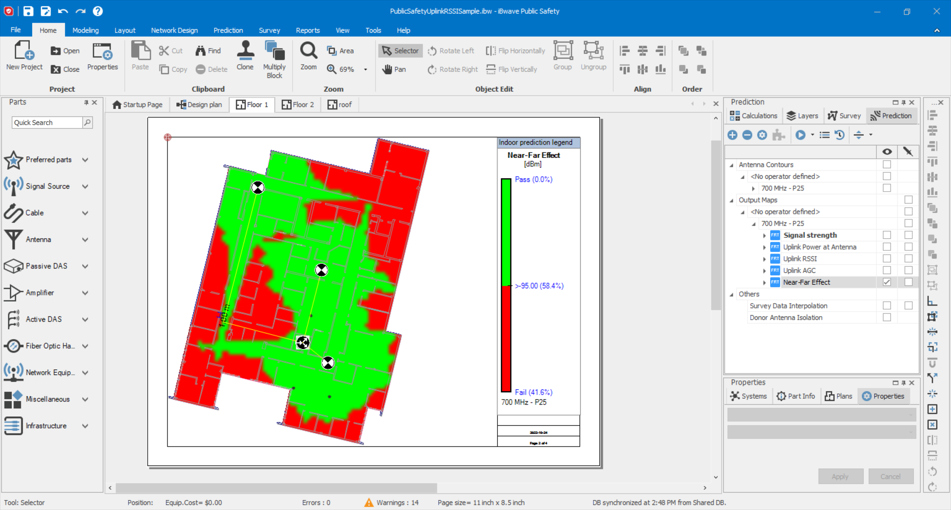
Near-Far Effect Map Captures Crucial Nuances
The near-far effect map shows when the proximity of one device to an antenna causes signal attenuation that affects a device that’s further away. When the signal strength gets modulated for the device closer to an access point, further devices in areas of poorer connectivity can lose their connection entirely.
Our near-far effect map captures this crucial nuance in public safety network design. Building off our AGC map, it gives designers the ability to accurately predict this more subtle cause of uplink failure.
And by presenting the information in a clear and comprehensive manner, it ensures the best possible chance of design approval by authorities. Rather than having to rely on heuristics, such as standardized antenna spacing that may not be relevant in a given deployment, an authorized employee can simply look at the map to see any potentially problematic areas. By avoiding dense, difficult-to-understand Excel spreadsheets, it minimizes the chance of misinterpretation of data.
Watch a demo of our Near-far Effect and Uplink AGC maps below:
iBwave Offers Comprehensive Uplink Mapping Capabilities for Network Designers
iBwave Public Safety design solutions put a full suite of uplink mapping tools into the hands of public safety network designers.
Interactive maps clearly show signal strength for designers and authorities and make it easy for designers to make changes and corrections during the design process. Easy-to-interpret maps ensure the best possible chance of success during the approval process and shortest possible turnaround time, accelerating implementation. We’ve also introduced a complete solution that simplifies surveying and grid testing public safety networks. Now you can get everything for surveying, grid testing and designing public safety networks under one family of iBwave products.
Check out our full range of public safety solutions for design and survey.
Rajeesh Radhakrishnan has over 18 years of experience in the telecom industry. At iBwave he is responsible for Presales and Engineering for India and Subcontinents. He also manages a customer support team of five people in India. As an expert in the field of indoor wired and wireless, Rajeesh is experienced in delivering projects covering multiple technologies and solutions such as Active/Passive DAS, FTTX, Wi-Fi, Small cell, and public safety.
Rajeesh joined iBwave’s Sales engineering team in December 2014 and received iBwave sales engineering awards for 2016,2017and 2018. Prior to iBwave, Rajeesh worked for a leading OEM, where he lead the RF Engineering team, delivering complex turnkey projects for multi-operator multi-technology telecommunication systems. Rajeesh played a key role for adopting iBwave solutions into the Reliance JIO the biggest 4G&5G operator in India. Rajeesh helped iBwave become a trusted advisor for the Indian telecom operator, enterprise segments and also with India's telecom regulatory authority. Rajeesh is an electrical engineer, he is also holds BICSI and Light brigade certifications.
- The Evolving Connectivity Landscape: Call for In-Building Design Validation from TRAI - April 25, 2025
- Making Smart Cities Smarter: The Role of Private Wireless Networks - January 25, 2024
- Building a Private Network: Step by Step - September 12, 2023


Good for you.